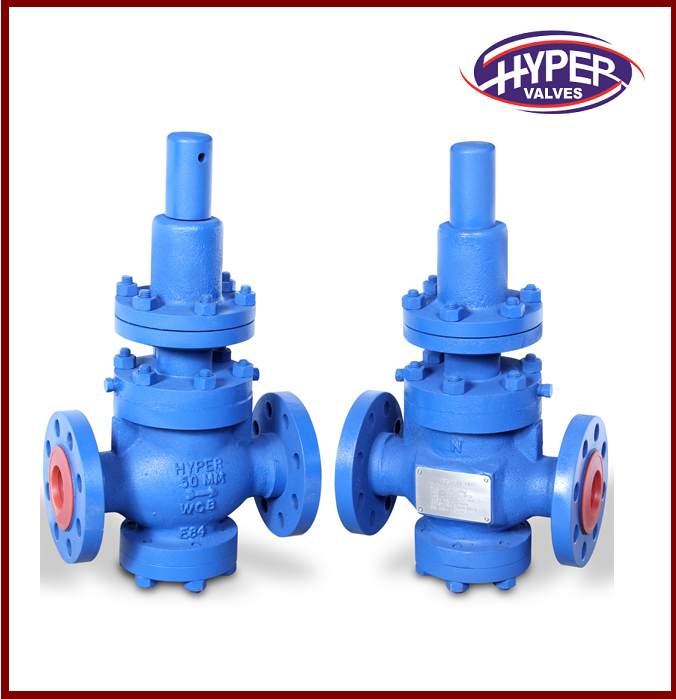
A
pressure relief valve is a device typically used to safeguard equipment from
internal overpressure. The varieties of pressure relief valves listed below are
the most regularly utilised in the market. There are a few concepts that need
be defined first before diving into the different types of Thermal Relief
Valve.
Back
pressure that's been applied
When the
pressure relief valve is closed, it creates static back pressure at the valve's
outlet.
Back
pressure that's built up over time
Pressure
loss at the exit of an open relief valve during discharge generates built-up
back pressure. Depending on the downstream pressure in the flare header, and
the flowrate of the relief valve being discharged, this pressure will vary.
When the
relief valve releases back pressure, the combined impacts of imposed and
built-up back pressure are present and felt.
Pressure
relief valves of the past (PRVs)
Changes
in back pressure have a direct impact on the pressure relief valve's
operational properties. Compared to a traditional safety relief valve, which
uses a built-up back pressure in addition to the superimposed back pressure to
determine the opening and set pressure values, the combined back pressure
affects the blowdown and re-seat pressure characteristics. It is not necessary
to employ a standard pressure relief valve when the backpressure is more than
10% of the set pressure at 10% overpressure (backpressure). If the overpressure
is greater than 10%, the maximum permissible built-up backpressure can be
increased.
Reliability
and adaptability are two advantages of using traditional relief valves. As long
as the sizing is done correctly, these relief valves are highly reliable and
versatile.
With
these relief valves, backpressure builds up on the valve's releasing pressure,
causing pressure buildup inside the protected equipment.
Balanced
relief valve for a blown bellows
The
incorporation of bellows reduces the impact of back pressure on the valve's
operational properties. There is an equal area of bellows around the entrance
orifice. Back pressure from the relief valve's discharge side is kept out of
this location. The air inside the bellows-enclosed chamber is free to circulate
as it pleases. As a result, the spring alone generates the opposing pressure on
the incoming fluid, with no help from any kind of backpressure. The permitted
back pressure for these relief valves ranges from 10% to 50% of the fixed
pressure.
Corrosion
danger is reduced since the bellows' discharge fluid is segregated from the
spring. When the relief valve is under a lot of combined backpressure, special
attention is paid to these relief valves.
The
disadvantage of using bellows is that they might wear out and fail, releasing
flammable or hazardous process fluids into the atmosphere when vented.
with a pilot
light as a safety relief valve
In order
to apply closing force to the safety valve disc, the process fluid is
circulated through a relief valve valve, which is connected to a pilot valve.
Consequently, the pilot valve serves as a safety device, complete with a
spring, when in use. Since there is no spring in the main valve, the process
fluid that flows through it acts as the main valve's operating mechanism.
Generally speaking, these relief valves are used in specialised applications
because the pressure drop across the inlet line of the relief valve is
significant (often larger than 3 percent of the set point) or the back pressure
is substantial. The highest amount of back pressure that may be endured is
typically greater than 50 percent of the original pressure applied.
Pilot
operated relief valves have the disadvantage of clogging the pilot valve input
and outlet tubes with foreign matter, such as hydration fluid, ice, wax, and
other substances.


