Friday, December 3, 2021

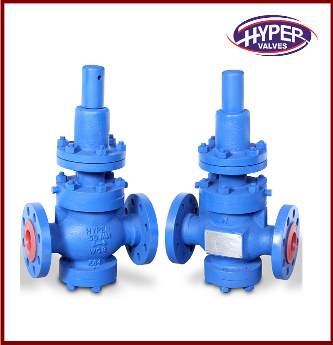
There are several different kinds of pressure relief valves.


A pressure relief valve is a device typically used to safeguard equipment from internal overpressure. The varieties of pressure relief valves listed below are the most regularly utilised in the market. There are a few concepts that need be defined first before diving into the different types of Thermal Relief Valve.

Back pressure that's been applied

When the pressure relief valve is closed, it creates static back pressure at the valve's outlet.

Back pressure that's built up over time

Pressure loss at the exit of an open relief valve during discharge generates built-up back pressure. Depending on the downstream pressure in the flare header, and the flowrate of the relief valve being discharged, this pressure will vary.

When the relief valve releases back pressure, the combined impacts of imposed and built-up back pressure are present and felt.

Pressure relief valves of the past (PRVs)

Changes in back pressure have a direct impact on the pressure relief valve's operational properties. Compared to a traditional safety relief valve, which uses a built-up back pressure in addition to the superimposed back pressure to determine the opening and set pressure values, the combined back pressure affects the blowdown and re-seat pressure characteristics. It is not necessary to employ a standard pressure relief valve when the backpressure is more than 10% of the set pressure at 10% overpressure (backpressure). If the overpressure is greater than 10%, the maximum permissible built-up backpressure can be increased.

Reliability and adaptability are two advantages of using traditional relief valves. As long as the sizing is done correctly, these relief valves are highly reliable and versatile.

With these relief valves, backpressure builds up on the valve's releasing pressure, causing pressure buildup inside the protected equipment.

Balanced relief valve for a blown bellows

The incorporation of bellows reduces the impact of back pressure on the valve's operational properties. There is an equal area of bellows around the entrance orifice. Back pressure from the relief valve's discharge side is kept out of this location. The air inside the bellows-enclosed chamber is free to circulate as it pleases. As a result, the spring alone generates the opposing pressure on the incoming fluid, with no help from any kind of backpressure. The permitted back pressure for these relief valves ranges from 10% to 50% of the fixed pressure.

Corrosion danger is reduced since the bellows' discharge fluid is segregated from the spring. When the relief valve is under a lot of combined backpressure, special attention is paid to these relief valves.

The disadvantage of using bellows is that they might wear out and fail, releasing flammable or hazardous process fluids into the atmosphere when vented.

with a pilot light as a safety relief valve

In order to apply closing force to the safety valve disc, the process fluid is circulated through a relief valve valve, which is connected to a pilot valve. Consequently, the pilot valve serves as a safety device, complete with a spring, when in use. Since there is no spring in the main valve, the process fluid that flows through it acts as the main valve's operating mechanism. Generally speaking, these relief valves are used in specialised applications because the pressure drop across the inlet line of the relief valve is significant (often larger than 3 percent of the set point) or the back pressure is substantial. The highest amount of back pressure that may be endured is typically greater than 50 percent of the original pressure applied.

Pilot operated relief valves have the disadvantage of clogging the pilot valve input and outlet tubes with foreign matter, such as hydration fluid, ice, wax, and other substances.

Monday, November 1, 2021

Breather valves are what they sound like.

 For atmospheric tanks and containers that fill and draw solvents at a high flow rate, the breather valve, also known as a pressure and vacuum relief valve, is a critical component. It is used in tanks, vessels, and process equipment in-and-out breathing lines to hold toxic vapours and avoid atmospheric pollution, balancing unexpected swings in pressure and vacuum, and offering greater fire protection and safety.

What is the function of the breathing valve?

It’s worth noting that the in- and out-breathing valves can be positioned side by side or overlapped in the breathing valve’s interior construction. As soon as the pressure in the tank is equal to air pressure, a “adsorption” effect occurs, which seals the seat tightly without allowing any escape. Due to the “adsorption” effect on the seat side, when the pressure or vacuum is increased, the disc opens and maintains a good seal.

Upon reaching the maximum permitted tank pressure, the pressure valve is opened and the gas is vented to atmosphere via tank’s vent valve’s side (namely the pressure valve). As a result of the positive tank pressure, the vacuum valve has been shut. At rising atmospheric temperatures, the liquid evaporation opens the vacuum valve, which allows the external gas to enter the tank via the suction valve (particularly the vacuum valve), closing the pressure switch. When the tank is completely full, the vacuum switch shuts. In contrast, the out-breathing process occurs when the tank is loaded. Pressure and vacuum cannot be opened simultaneously at the same time.

What is the function of the breather?

Only if the following occurs will the breathing valve be sealed when used in typical circumstances:

1. The breathing valve inhales air or nitrogen into the tank while the tank is bleeding.

2. breathing valve starts releasing exhaled gas as soon as tank is filled.

3. The liquid in the tank evaporates rapidly when exposed to hot breathed gas in an emergency. The respiration valve opens to allow the liquid to escape before it is damaged by overpressure.

What is the procedure for installing the breather valve?

1. The breathing valve must be mounted at the tank’s highest point, towards the top. Although this isn’t always practical, the pressure reducing valve should be placed as high as possible to allow the most direct and easy access to it when it comes to lowering evaporation losses.

2. Tanks with a big volume can have two breathing valves installed to prevent failure of a single breath valve due to overpressure or negative pressure. Two breathing valves operating at the same time increases the possibility of failure, hence most systems use a gradient-type design with one running regularly and one as a backup.

3. There should be two or more valves if one does not match the criteria due to a high breathing volume.

4. If the breathing valve has an arrestor, the effect of the arrestor’s pressure decrease on the breathing valve’s discharge pressure must be taken into account to prevent the tank from going over pressure.

5. The breather valve in tanks with mean temperature less than or equal to zero must have anti-freezing measures installed to prevent the tank from refrigerating or blocking the nozzle disc as a result of inadequate exhaust or an inadequate air supply, actually results in an overpressure percussion tank or a pressure losses deflated tank.

Friday, October 29, 2021

Types of Safety Valves


Safeguard valves are available in various designs to satisfy the needs of multiple applications and performance criteria in various industries. The numerous varieties of safety valves described by national standards, each with its own unique set of features, can be found in international standards—every one of them.

ANSI/ASME PTC 25.3 describes relief and safety valves for boiler and pressure vessel applications while ASME standard I and standards VIII provide the following specification. These standards specify the safety valve performance parameters and the various safety valve types that can be utilised. Boiler safety relief valves must open within 3 per cent of the maximum operating pressure and close within 4 per cent of the maximum working pressure according to Section I of the ASME pressure vessel code. To be approved by the National Board of Standards, it must have two blowdown rings and be stamped with a "V."

ASM Pressure Vessel Code, Section VIII: Design and Construction For pressure vessel applications, Section VIII safety relief valves are designed to open at 10% overpressure and close at 7% overpressure. When it comes to identifying the National Board, they utilise a unique 'UV' stamp. A valve with a tiny discharge area has a discharge area determined by the actual location of the valve disc.

While the safety valve is fully open, the disc position has no impact on the discharge zone.

A "full bore safety valve" must have no protrusions in the bore and a height high enough for the least feasible area to operate as the controlling orifice at any segment, whether above or below the seat, to be called a "full bore" safety valve.

Backpressure to the valve has a direct effect on how effectively it performs because of the traditional design.

One of the primary functions of the safety valve is to restrict the impact of backpressure on its operational qualities. Valves that provide pressure relief while also providing safety:

It is also used in conjunction with and charge of self-activated auxiliary pressure relief valves. Pilot-operated pressure relief valves

As the name implies, this pressure relief valve has a secondary pressure-relieving mechanism operated by a separate device powered from outside the valve.


In Germany and other European countries, safety valves sold under the DIN 3320 standard include the following:

A conventional safety valve has the lift required to discharge the mass flow rate within a pressure rise of no more than 10% of the operating pressure when it is opened. It is also known as a high lift valve because of the popping sound when it opens or closes).

The total lift safety valve will swiftly open to the design's maximum lift if the pressure rises by at least 5%. Only a maximum of 20% of the total charge will be used for the quick opening (proportional range).

To keep the valve closed, a "direct loaded" safety valve uses a closing force (such as a spring or weight) to counterbalance an opening force (under the valve disc).

As a result of a change in pressure, proper safety valves open more or less continuously. If the lift range is between 10% and 20%, no quick opening will occur unless pressure increases. These safety valves provide the lift required to discharge the mass flow after being opened to a pressure exceeding 10% of the working force.

An anti-flood safety valve, which has an inflatable diaphragm, protects linear elements in motion as well as springs.

A direct-loaded safety valve's protective bellows shields moving and rotating parts, as well as springs, from fluid flow.

An Automatic Control Valve can be controlled by either a motor or a microcontroller. These safety valves use a supplementary force to raise the closing party until they reach a predetermined pressure, after which they lose some of their closing force.

The following types of safety valves are recognised by EN ISO 4126:


It is possible to maintain safe pressure by utilising a safety valve that releases a tiny amount of fluid to help keep the system safe and then closes again to prevent further fluid flow. Look for a valve that opens quickly or as a result of increased pressure above a predetermined limit when recognising one (not necessarily in a linear fashion).

The fluid pressure under the valve disc is only loaded by a direct mechanical loading device, such as a spring, when you have a safety valve with immediate automatic loading.

Even if the powered assistance mechanism fails, safely valves with powered aid mechanisms can be raised to pressures lower than the present pressure and still meet all safety valve parameters in the standard. valves with aid for safety

The safety valve receives an additional push when the pressure at the inlet reaches a certain pressure. The other force improves the sealing strength of the valve.

An additional force (extra load), provided by an external power source and reaches a certain level when the safety valve's input pressure increases, is securely released. If additional loading isn't discharged, the safety valve's design limits its authorised discharge capacity to 1.1 times the maximum permitted pressure of the equipment it's supposed to safeguard.

Tuesday, October 5, 2021

What are the functions of breather valves?


Breather Valves, also known as direct-acting Pressure/Vacuum Relief Valves, are specialized forms of pressure reducing valve developed for tank protection. Pressure, vacuum simply, and pressure/vacuum mixed valves are offered with flanged channels or vented to the atmosphere.

To reduce evaporation loss, pressure relief controllers are widely employed on bulk storage space tanks, as well as fixed roof reservoirs with floating covers. The Valves protect the system from becoming unbalanced or damaging the storage vessel by preventing excessive pressure or vacuum build-up.

Weighted pallets or springs control pressure and vacuum protection levels combined to produce the needed Pressure/Vacuum settings. It is typical to combine the pallet and spring systems in one unit; for example, pressure settings require a spring section, while vacuum settings require the pallet approach.

What are the benefits of using Breather Valves?


The Breather Valve is a safety device positioned on a nozzle opening on the top of an atmospheric storage tank with a permanent roof. Its primary purpose is to keep the tank from bursting or imploding.

A fixed roof atmospheric tank would explode without an opening or a controlled opening due to increased pressure induced by pumping liquid into the tank or vapor pressure changes caused by severe heat changes. Implosion, or the collapse of a tank, occurs due to pumping out or thermal changes. The vapor space pressure falls below atmospheric pressure as the liquid level drops.

This vacuum must be relieved by opening the tank in a controlled manner. In other words, the tank must be able to breathe to avoid bursting or imploding. This Valve is known as a Breather Valve because of its principal purpose.

The American Petroleum Institute Standard API 2000 or another applicable standard should be followed while selecting valves.

How do Breather Valveswork?

In most atmospheric tanks, a venting mechanism is required to allow vast volumes of vapor to escape at low pressures. The permitted set pressure is usually expressed in inches of water column pressure for favorable and vacuum circumstances. Because most big storage tanks have a low maximum permissible working pressure, this is the case.

These tanks are typically large-volume welded vessels built to API 650 specifications. These Valves have larger ports than the inlet or nozzle connection to accommodate significant volumes at low set pressures. Because of the low setting, the Valve must be weight-loaded rather than spring-loaded. As a result of those above, a Breather Valve requires around 100 percent over set pressure to open fully.

To achieve optimum flow, the weight-packed Valve process MAWP should be at slightest twice the needed set pressure when deciding on set pressure. If the MAWP is less than 100% of the required set, the Valve may need to be larger than it usually is. If less than 20% overpressure is allowed, valve chatter and rapid seat and diaphragm degradation are possible. Simply put, a Pressure/Vacuum Valve differs from a high-pressure safety Relief Valve in that it should not be sized at 10% or 20% overpressure. Consult the manufacturer's flow curves for sizing a Pressure/Vacuum Valve, and allow enough overset pressure.


Water pressure reduction valves are small, low-cost regulators that serve two purposes.


1. They reduce the high incoming water pressure from city mains to a lower, more functional pressure for housing distribution.

2. They control by keeping a constant pressure in homes, ensuring that piping and appliances are kept at a safe operating pressure.

The following are some of the benefitss of placing Pressure Vacuum Relief Valve on your home's fixtures:

It conserves water. The volume of water that flows out of a fixture is reduced via pressure-reducing valves. This is especially useful for appliances like washing machines and dishwashers, which may quickly become swamped with water.

It conserves energy. Because pressure-reducing valves have been placed, less water moves through the plumbing system, which means less hot water and energy are needed. When pressure-reducing valves are fitted, the water flow is reduced by 30%, according to the EPA, which equates to a 30% reduction in the electricity cost.


It conserves water. Water used in sinks, showers, and baths is transported to a wastewater treatment facility or a home's septic system. Installing pressure-reducing valves reduces the volume of wastewater in both cases, which is good for the environment.

Because water with a strong push behind it can erode or wear away materials, high water pressure can harm a home's plumbing system. This could result in leaking water heaters, leaking pipes, dripping faucets, and appliance failure. Excessive water flow is harmful, wasteful, and shortens the life of equipment in the system. If you hear pounding pipes or see water splashing in your sink, you have excessive water pressure in your home. Your local plumber can use a gauge to test your stress for a more accurate reading.

Calling the expert team at hyper valves for a quote and advice on the numerous types of Sanitary Pressure Relief Valve available and which one is most suited for your home is the most straightforward approach to get pressure reducing valves fitted.

Wednesday, August 18, 2021

Pressure Regulator vs. Pressure Control Valve: What's the Difference?


PTFE Lined Pressure Relief Valve regulates fluid flow by opening or closing a valve in response to an electrical signal created by a process variable (temperature, pressure, or level). The process directly controls a regulator.

A pressure regulator, for example, does not require external power to operate; instead, pressure from the fluid on the diaphragm activates the open/close action of the valves.


If the pressure in the pipeline is equal to or slightly below the set point pressure, the PCV will open an output valve to let hydrocarbons. Maintaining a safe transit pressure and correct metering of the item are both aided by automating fluid control in this manner.

Although they operate differently, both a pressure relief valve (PRV) and a pressure control valve (PCV) are used to control pressure.

A PCV is the first line of defense in an oil field, preventing hydrocarbons from flowing through a channel under pressure. A PRV is a static secondary safety device used to 'bleed out' excess pressure from a pressurized system or an oil and gas well.

Pressure Relief Valve vs. Pressure Regulator

A pressure regulator differs from a pressure relief valve in several ways. A pressure regulator, like a PCV, is primary safety equipment used in oil and gas facilities to control pressure. On the other hand, a PRV is a secondary safety device that controls secondary (non-critical) pressure.

Safety Valve for Pressure (PSV)


A pressure safety valveis an instinctive safety device that immediately relieves pressure on a squeezable fluid vessel to prevent critical failure and death from over pressurized vessel conditions.

What is the difference between PCV and PSV?

In terms of function, a PSV and a PCV are very similar. The fundamental difference between a PSV and a PCV is that a PSV's valves open almost wholly when the fluid reaches the setpoint temperature. A PCV's valves open gradually.

Choosing the Correct Control Instrument – Response Time

Pressure regulating valve have a faster reaction time than pressure control valves because they are process-controlled and do not require an intermediate relay system for control.

Continuity between DCS, sensors, and actuators is required for PCVs. As a result, when one component fails, the entire system is vulnerable to instrumentation failure.

What is the goal of a control valve?


A control valve manages fluid flow by changing its size or direction in response to controller input. It aids in the direct control of flow rate and the regulation of other critical process variables, including temperature, liquid level/flow, and pressure. In automatic control terminology, it is also known as the "final control element."

In other words, a Safety Valve is used to regulate the flow, pressure, liquid level, and temperature of a system by entirely or partially opening or closing it in response to controller signals. The positioners control the closing and opening of the electric, hydraulic, and pneumatic actuators, which govern the opening and shutting of the control valve.

How does it work?

To offer constant quality goods, the process plant has several control loops. These control loops have a predetermined pressure, temperature, flow, and level to maintain the desired working range. Internal disturbances occur in each of these control loops, which are monitored by sensors and transmitters. The controllers subsequently analyze the acquired data, who determine what should be done to correct the load disruptions. A controlling element is implemented after the data has been examined, measured, compared, and calculated. The control valve enters the scene at this point and works to lessen the disturbances


As a result, the control valve's working concept relies on manipulating flowing fluids like water, gas, steam, or chemical compounds to guarantee that load disturbance is minimized, and the process variable is regulated to the closest value of the desired set point.

Gate valves are used to open and close doors.

The Automatic Control Valve is made up of a flat barrier that may change the flow area. It has an on-off application and is well suited to regulate high temperature and pressure for various liquid flows. The valves that regulate the automated emergency cut-off and the hand-operated valves have this design or body.

THE BENEFITS OF A GATE VALVE

·         It features an excellent Closing feature.

·         In a circuit, it can be used in either direction.

·         It creates laminar flow, resulting in minimal pressure loss.


GLOBE VALVE


The phrase "globe valve" refers to the outer shape of the valve, which is utilized for throttling. The globe valves have a stem that moves up and down in a linear motion to modify the position of the plug. It has a short stem journey, a lot of seating capacity, a lot of pressure drop, and flow controllability.

THE BENEFITS OF A GLOBE VALVE

·         Has an excellent full-closing feature.

·         Because the strokes are more minor, the valve opens and closes faster than a gate valve.

·         Has a practical throttling feature.

·         With little change in shaft disconnection, it can be used as a stop check valve.

PLUG VALVES


Plug valves are made up of a plug, a body, and a cover and are used for on-off services in refineries, chemical plants, and petrochemical plants. Typically tiny in size, they require less headroom and come in a variety of materials. They provide a tight seal, rapid opening, and minimal pressure drop.

·         It is made up of only a few elements and has a straightforward design.

·         Easily opens and closes.

·         It is simple to maintain and repair at the location of operation.

·         They offer a low flow resistance and a leak-proof feature that is trustworthy.

BALL VALVES


The pressure and flow of corrosive fluids, regular liquids, gases, and slurries are controlled by a ball valve. It also keeps high temperatures and stress under control.


BALL VALVES HAVE MANY BENEFITS

·         Provides a leak-free service.

·         Service that is quick to open and close.

·         When compared to gate valves, it has a relatively modest size.

·         In comparison to gate valves, it is lightweight.

·         Has the ability to reduce the number of valves necessary by using a multi-way design.

·         Under high temperature and pressure conditions, it provides dependable and safe service.

·         When compared to gate and globe valves, it requires less force to operate.

DIAPHRAGM VALVES

For corrosive fluids at low temperatures and pressures, a diaphragm valve is utilized by deforming one surface with force from the valve stem.

ADVANTAGES OF DIAPHRAGM VALVES

·         The diaphragm isolates the working parts from the process fluids completely.

·         Construction is simple, making it easier to operate and maintain.

·         It has hassle-free functioning due to its basic design and convenience of use.

·         It can be utilized for a variety of purposes, including opening, throttling, and closing.

·         It provides solid chemical resistance because it is based on the body's internal sheathing.

·         There is no shaft leakage since the fluid is kept separate from the bonnet group.

·         Heavy chemical, chemical, and radioactive fluids are all compatible.

·         It can protect the system from microbiological contamination because the fluid is kept apart from the bonnet group, and it can be utilized in the food, pharmaceutical, and beer industries.


Wednesday, May 5, 2021

Knowing what a pressure safety valve is and what are its uses


The industrial piping systems in various industries have many types of hot and pressurized fluid substances such as liquid or gas flowing through them. If somehow the pressure of the fluid increases due to temperature rise then the gas will also expand. If there is no space for a gas outlet then the gas will eventually explode out of the pipe resulting in dangerous outcomes within the factory premises.

Of course, you want to avoid such critical scenarios to prevent your inventory damage and the providing better safety of work for the laborers.

Well, this is what a Pressure Sustaining Valve is used for.

Defining what a pressure sustaining valve is all about

A valve that sustains pressure will have predetermined maximum levels. If the pressure of the gas goes beyond that then the valve mouth opens up releasing the extra pressure.

Knowing the use of a pressure safety valve

The Pressure Vacuum Relief Valve is solely installed for safety purposes. The fundamental use for installing valves in pipe systems is to ensure that they do not explode under extreme gas pressure inside causing severe damage to piping systems upon excess heating of the gas.

Tuesday, April 6, 2021

What are automatic control valves?


Automatic control valves (or control nozzles) are basically small sized valves used in gas or liquid services. Since this type of valve has a fly-threading stem, a larger seat area will help you with a certain resistance flow. There are different types of needle valves available in the market. These nozzles differ in their size, function, shape etc.

Basically, needle valves are used to control the flow of gases and liquids at low rates. The large seat area of ​​this valve and the finely threaded stem will help you with a certain resistance to flow. Such a valve design is also used to control the flow of fluid in a delicate gauge that can be damaged by a sudden increase in fluid, which will remain at high pressure. The Automatic control Valve is also the best option for working in high pressure conditions.

With the help of needle nozzle and breather valve, you also have the option to stop the flow. You can also make some specific adjustments in this valve to maintain fluid flow. There are also needle valves and hydraulic valves, which are obtained to control the flow of water. Moreover, most of these valves do not require any additional power source for operation.

Wednesday, January 6, 2021

What are safety relief valves and what are their various industrial applications?


A Safety Relief Valve in India also known by the name of pressure relief valve is a safety device that regulates the pressure and checks the unwanted occasions of pressure or temperature rising within industrial equipment or device. 

Safety Relief Valves Suppliers in  India manufacture different types of safety valves based on the type of device and the minimum and maximum operating pressure range of a device.

If it were to not be installed in your pressurized industrial equipment it would result in excess pressure being blasted out of the equipment that can lead to fire hazards within the industrial premises, equipment failure, and other hazards that relate to a safe working environment within the industrial premises.

Industries that use a safety relief valve

There are various industrial uses of the safety relief valves in India. Based on the application of the device and the industry they are in they can be fitted with various grades of safety relief valves that operate within a range of pressure and temperature.

They can be fitted in various refineries, petrochemical industries, chemical manufacturing industries, natural gas manufacturing equipment and devices, power plant equipment, power distribution companies, hydroelectric power plants, food manufacturing and food waste processing machines, pharmaceutical industries, and other industries.